
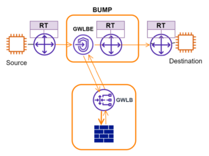
AWS GWLB provides a new way to integrate third-party security appliances. Widely documented inspection patterns include Internet inbound, Internet outbound, and east-west traffic between VPCs. In the previous blog, I illustrated the three flow patterns using the wire-in-the-bump concept. This leaves out a major category of use cases where Intra-VPC East-West inspection is needed. It is a concern with the increasingly popular Shared VPC architecture. In this blog, I’m sharing my trial and error experiences on this topic.
Introduction of Basic Use case
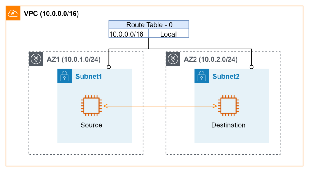
Figure 1 illustrates a very basic use case. Two workloads are deployed in separated AWS availability zones (AZs). The requirement is to inspect bidirectional traffic between them. The assumption is that either workload can initiate requests. For illustration purposes in this blog, I designate one side as the source and the other as the destination. The setup implies the two workloads are NOT on the same subnet. Otherwise, it is not feasible to divert traffic to GWLBE.
Attempt #1 Partition Application by AZ
Let’s start with the simple case where all applications are deployed in a single AZ. In the traditional on-prem world, this is equivalent to running all workloads in one data center. There is one or one pair of firewall appliances. GWLBE setup is fairly easy using the same on-prem model. All inter-subnet traffic that requires inspection can use a single GWLBE as the next hop. AWS offers a VPC enhancement where more specific routes than VPC CIDR can be defined in Route Table.
What happens when an application requires high availability of multiple AZs (ie multiple data centers)? In my experience with traditional on-prem data centers, routing design needs much more careful planning to keep traffic symmetry for stateful firewall inspections. To cope with challenges, AWS has the recommendation of Availability Zone Independent (AZI) architecture. This approach partitions application components into individual zonal services by AZ boundary. For an example of a two-tier application and DB design, App instances in AZ1 only communicate with DB instances in AZ1. Similarly, App instances in AZ2 only use DB instances in AZ2. In essence, the multiple-AZ (data center) complexity is simplified into independent AZs where traffic does not cross the AZ boundary.
This approach is applicable when it’s possible to keep traffic locality inside an application. In most application design patterns I have seen, a tier is typically loosely coupled with other tiers in terms of high availability. Geo locality is preferred in normal running conditions. When failure occurs, the tier would offer its service from other locations rather than fail together with its consumers. Moreover, it’s hard to control traffic locality for inter-application communications when the number of applications grows in a VPC.
Attempt #2 Bump-in-the-wire through one AZ
Figure 2 shows the design where all AZs point to a single GWLBE in one AZ. In on-prem reference, this is similar to the central inspection model. Traffic from spoke data centers is sent back to the hub location for inspection. The SLA in this approach relies on the underlay AWS infrastructure. The chance of losing AWS AZ is arguably small. Even in that worst-case scenario, I would simply update route tables and point next-hops to new GWLBE in a different AWS AZ. This is a good compromise between complexity and SLA.
Attempt #3 Bump-in-the-wire using Local AZ – Failed Attempt due to Asymmetric Routing
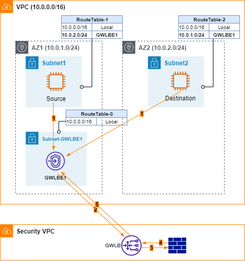
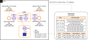
Now the experiments start to get more interesting. Is there a way to forward traffic to GWLBE in the respective local AZ? In Figure 3, ping is performed on Source EC2 to Destination EC2. Traffic flows are listed below.
- ICMP requests go from source to GWBE1.
- GWLBE1 forwards incoming traffic to GWLB through AWS private link.
- GWLB sends traffic to FW through GENEVE overlay.
- FW inspects and responds.
- GWLB sends traffic back to GWLBE1.
- GWLBE1 uses its RouteTable to send traffic to Destination EC2. On Destination EC2, tcpdump confirms incoming ICMP requests. Destination EC2 generates ICMP responses.
- I expect Destination EC2 would follow RouteTable-2 and sends ICMP responses to GWLBE2. However, I fail to find corresponding records in GWLBE2’s flow log data. According to my communication with AWS, GWLBE somehow keeps its state table. Since it does not have ICMP requests tracked, ICMP responses are dropped. Well, I’d hoped AWS underlay network would not care about flow states so I only need to focus on symmetric routing for GWLB/FW. Apparently, that’s not the case. Lesson learned. It is critical to keep routing symmetry along network paths.
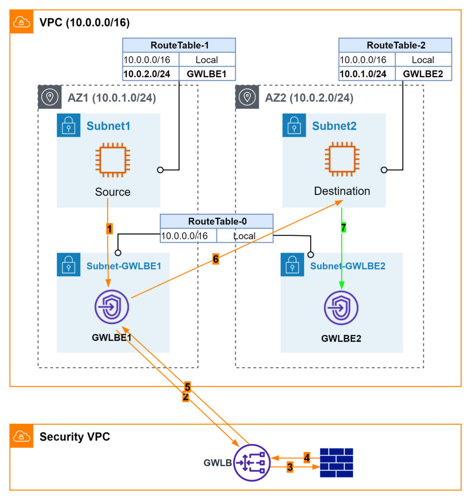
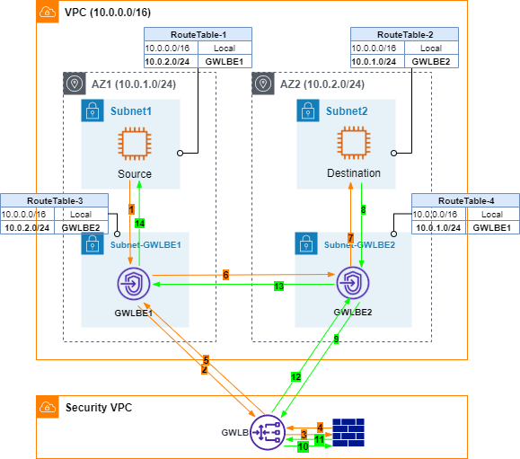
Attempt #4 Bump-in-the-wire in both AZs
I am the type of person who does not give up easily. To work around the asymmetric routing issue, I started to think about how to solve this challenge if this were on-prem. Maybe I need one Firewall in each data center? To mimic that, I point GWLBE at each other as the next hop.
Let’s review traffic flows in this case.
- ICMP requests go from source to GWBE1.
- GWLBE1 forwards incoming traffic to GWLB through AWS private link.
- GWLB sends traffic to FW through GENEVE overlay.
- FW inspects and responds.
- GWLB sends traffic back to GWLBE1.
- According to RouteTable-3, GWLBE1 forwards traffic to GWLBE2.
- GWLBE2 forwards traffic to Destination EC2.
- Destination EC2 responds ICMP requests.
- GWLBE2 sends responses to GWLB through AWS private link
- GWLB sends traffic to FW through GENEVE overlay.
- FW inspects and responds. Note here both ICMP requests and responses traverse through the same GENEVE interface. FW is able to maintain its state properly.
- GWLB forwards responses back to GWLBE2.
- GWLBE2 looks up RouteTable-4 and uses GWLBE1 as the next hop.
- Finally, GWLBE1 sends ICMP responses back to Source EC2. Pings are successful.
Additional successful TCP tests (ie ssh and https) between Source and Destination further demonstrate symmetric routing at AWS underlay network layer and FW appliance.
I only show two AZs in Figure 4. Should there be more AZs, it would be a mesh topology among all GWLBEs. Note AWS does not support dynamic routing protocol in its Route Table. All GWLBEs are configured as static routes. I do not have a way to simulate AWS AZ failure. In that case, I assume traffic would continue forwarded to failed AZ and timed out. Either the consumer side or producer side can provide fail-over logic to re-direct traffic to healthy AZs.
Attempt #5 Route through FW – Not Supported by Palo Alto PanOS
Even though I hold this attempt to last, it’s the first idea coming to my mind. I guess it’s pretty natural for folks familiar with traditional zone-based FW design. I would treat Source subnet/AZ1 and Destination subnet/AZ2 as two security zones. In Palo, I map GWLBE1 as a sub-interface and assign it to Zone1. Then I repeat GWLBE2 as another sub-interface and assign it to Zone2. Unfortunately, PanOS does not support routing between two GENEVE (sub)interfaces as of my tests. Palo’s overlay routing is only available between GENEVE and non-GENEVE interfaces.
Takeaways
Shared VPC is one important AWS network design pattern. As demonstrated from my experiments, inspecting intra-VPC traffic is not straightforward. AWS has done an excellent job making AZ consumption so transparent that most users do not ever pay attention to it. In reality, AZ is still a data center and subject to some very same traditional network constraints. I have to acknowledge I had not spent enough time on the intricacy of multiple-AZ networking until I worked on GWLB/firewall design.
So which approach I’d suggest? Depending on the deployment scale, HA/SLA requirements, and operational complexity, I would not mind a combination of the above patterns. It’s also beneficial to debate the shared VPC model for applications with very strict security and inspection requirements.
Additional Considerations.
Below considerations are quoted from AWS blog for AWS Network Firewall deployments. All the fine-prints are still valid for third-party GWLB integrations. I have to repeat my point. “Pay attention to Symmetric Routing“!!!
- Use SGs and network ACLs where possible and implement inter-subnet (east-west) inspection only where necessary.
- Once a firewall endpoint (or any other middlebox) is inserted into your traffic flow, security group referencing cannot be used to allow source to connect to your destination. You can use IP addresses of your source in the security groups to permit the incoming traffic.
- Traffic between NLB and backends of instance target type does not follow VPC route table routes. If you want to inspect traffic between NLB and backends, use IP target type.
- When adding routes more specific than VPC CIDR, each route destination must match existing subnet CIDR.
- Default number of routes per route table is 50. You can increase it up to 1,000.
If there are other design patterns I should play with, please feel free to leave your comments.
Hi Lixun,
Thanks a lot for posting such a useful guide on different scenarios. I’m trying to implement your Attempt #4, bump in wire in both AZs. For my scenario, I’m trying to route subnets within same VPC to GWLBE and default route to Transit Gateway. However, as soon as I add routes of other subnets pointing to GWLBE, traffic for 0.0.0.0/0 also gets forwarded to GWLBE and I lose connectivity to my test EC2 instances. As soon as I remove the inter-subnet routes, connectivity is restored.
Did you face such issue? If yes, what did you do to resolve it?
Thanks in advance!
Hi Jay, it would help if you share your RT setup. Does your test EC2 instance happen to be on any of the inter-subnet ranges? Unless you have a more specific route (MSR), traffic should follow 0/0.